
PIGGYBACK ENGINE MANAGEMENT · OEM/ODM
Piggyback ECU Systems for Configurable Engine Tuning
A piggyback ECU works with the factory engine control unit to modify selected sensor or control signals. LikedLinking supplies configurable piggyback engine management hardware, universal and project-specific wiring options, sample evaluation from one unit, and OEM/ODM support for tuners, distributors and performance vehicle integrators.
- MOQ 1Sample evaluation
- ConfigurableFuel, ignition and signal control
- OEM/ODMHardware, harness and branding
A FOCUSED CONTROL LAYER
What Is a Piggyback ECU?
A piggyback ECU is an aftermarket engine tuning module installed alongside the vehicle’s original ECU. Instead of taking over every engine-management function, the piggyback controller intercepts, conditions or modifies selected signals. Depending on the confirmed hardware and application, those signals may relate to airflow, manifold pressure, fuel delivery, ignition timing or other tunable functions.
This architecture can be useful when the project needs more tuning flexibility but still depends on factory functions managed by the original ECU. It can also provide a practical development route for turbo conversions, modified intake and exhaust systems, fuel-system changes, specialist vehicles and low-volume performance projects. Compatibility, available functions and calibration method must always be confirmed for the actual engine, original ECU, sensors and wiring arrangement.
PUBLISHED PRODUCT PAGES
Compare Piggyback ECU Controllers: AEM, GReddy and JSCHIP
Each product below has its own details and image. Confirm the controller version, wiring, engine and original ECU before ordering.
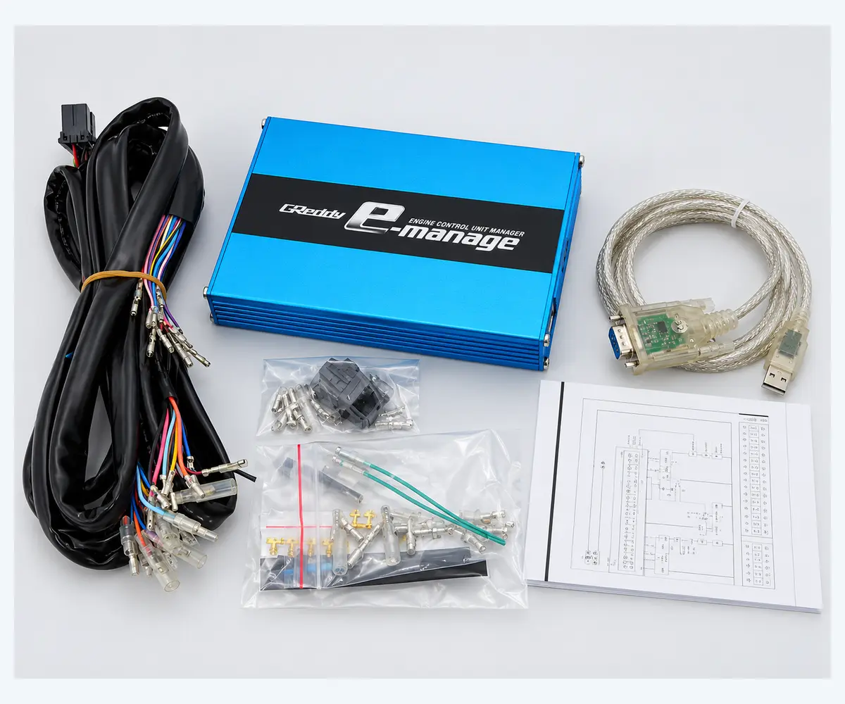
Universal Piggyback ECU
View product details →
Pajero iO Piggyback ECU Kit
View product details →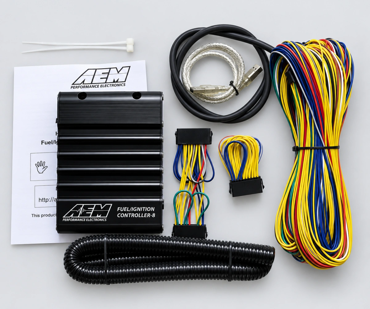
AEM F/IC-8 Controller
View product details →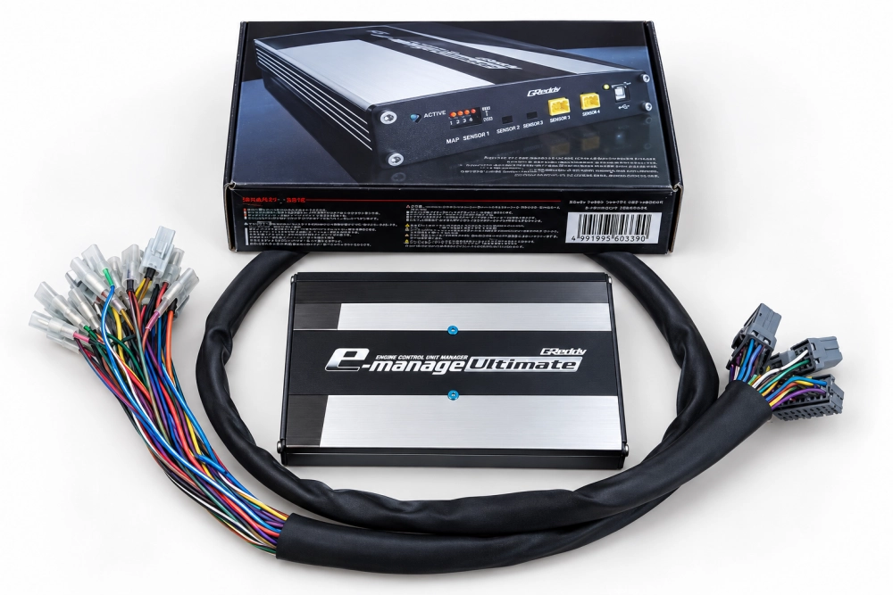
GReddy e-Manage Ultimate Piggyback ECU
Fuel, ignition and signal tuning with a confirmed harness and factory ECU.
View GReddy product details →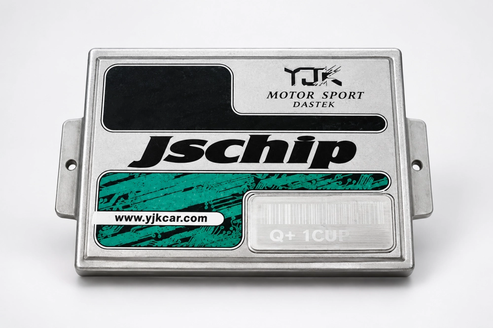
JSCHIP Piggyback ECU
A separate piggyback engine management option for reviewed vehicle and wiring details.
View JSCHIP product details →MEASUREMENT FOR CALIBRATION
Using a Wideband Air Fuel Ratio Gauge with a Piggyback ECU
A wideband air fuel ratio gauge kit lets a tuner observe AFR or lambda while evaluating a piggyback ECU calibration. It measures the mixture; it does not control fuel injection or ignition by itself. Match the AEM gauge model and oxygen sensor first, then confirm how its output can be logged alongside engine load and RPM. The GReddy e-Manage Ultimate, JSCHIP and AEM F/IC-8 pages describe controllers with different wiring and control scopes, so check the actual engine and factory ECU before comparing them.
MATCH THE CONTROLLER TO THE ENGINE
Piggyback ECU Selection for 4, 6 and 8 Cylinder Engines
Four-cylinder, six-cylinder, eight-cylinder and turbo describe application requirements, not four separate LikedLinking products. Choose an actual controller from the product pages above, then confirm its available channels, signal types and harness against your vehicle. The engine’s cylinder count alone does not establish compatibility.
Review factory ECU pinout, injector and ignition wiring, sensors and whether the engine is naturally aspirated or turbocharged.
Confirm the number of controlled fuel and ignition channels, trigger arrangement and harness before selecting a piggyback ECU.
Check controller channel capacity and the exact features of the quoted version. The AEM F/IC-8 product page discusses one relevant controller.
Review pressure sensing, fuel supply, ignition strategy, AFR measurement and the factory ECU’s monitoring before any calibration plan.
Send your vehicle, engine code, original ECU and wiring details for a controller and harness compatibility review.
CONTROL CAPABILITY
Functions Confirmed Around the Actual Engine
A product name alone does not establish compatibility. The available functions depend on hardware configuration, signal type, original ECU strategy and calibration resources.
Fuel Signal Adjustment
A piggyback fuel controller may modify selected load, airflow or injection-related signals to support a revised fuel strategy. Injector type, fuel pressure, sensor feedback and tuning method still need to be evaluated.
Ignition Timing Control
Some configurations can provide ignition-related adjustment for compatible trigger and control arrangements. The precise authority and connection method must be verified before supply.
MAP and Airflow Signals
MAP, MAF, TPS and other engine-load inputs can be central to piggyback ECU tuning. Sensor range, output curve, wiring and factory ECU plausibility checks affect the solution.
Turbo and Boost Projects
Forced-induction applications may require coordinated attention to manifold pressure, fueling, ignition, boost hardware and wideband AFR feedback rather than a single isolated adjustment.
HOW IT WORKS
Piggyback Engine Management Without Replacing Every Factory Function
The controller is wired into selected circuits between the vehicle sensors, the original ECU and/or supported engine outputs. It processes the configured signals and applies an agreed adjustment strategy while the factory ECU remains part of the system.
This is different from a standalone ECU, which normally assumes broader control of engine operation. A piggyback tuner can therefore be attractive where the original ECU must continue handling functions such as instrument communication, body integration, diagnostics or other factory systems. However, the retained ECU may monitor expected signal ranges, so installation and calibration must be performed carefully.
SELECTION GUIDE
Information Needed Before We Recommend a Piggyback ECU
Accurate application data prevents mismatched connectors, unsupported signals and unrealistic product claims.
QUICK INQUIRY CHECKLIST
Send These Six Items
- Vehicle model and year
- Engine code and cylinders
- Factory ECU photos
- Turbo or naturally aspirated
- Functions you want to adjust
- Quantity and destination
CONTROLLER + WIRING
The Harness Is Part of the Piggyback ECU System
Reliable engine tuning requires more than a controller enclosure. Connector choice, pin mapping, wire quality, shielding, branch lengths, grounding and labeling directly affect installation and signal integrity.
Universal Flying-Lead Harness
For experienced installers building a custom connection around confirmed signals and pin assignments.
ECU Adapter or Patch Harness
Connects between known interfaces when both connector ends and the required pinout have been verified.
Vehicle-Specific Harness
Available only after exact model year, engine, ECU connector and retained functions have been confirmed.
Custom OEM/ODM Harness
Connector, branch, length, label, sleeving and packaging options can be reviewed for repeat supply.
FROM SAMPLE TO SUPPLY
A Controlled Four-Step Process
We start from the application rather than assuming that one piggyback ECU fits every vehicle.
- 01
Define
Share the vehicle, engine, original ECU, current modifications and tuning objective.
- 02
Review
We review the controller architecture, required channels, connectors and wiring method.
- 03
Evaluate
Begin with one agreed sample where available and complete installation and calibration testing.
- 04
Repeat
After confirmation, align the configuration, harness, labels, documentation and order plan.
PIGGYBACK ECU FAQ
Questions Buyers Ask Before Ordering
Use these answers as a starting point. Final compatibility is based on the real application data.
Ask a Technical QuestionA piggyback ECU works alongside the factory ECU and adjusts selected signals or functions. A standalone ECU normally replaces the primary engine-control strategy and offers broader authority. The correct option depends on the vehicle, required control, wiring and calibration resources.
No. Engine configuration, signal type, original ECU logic, connectors and required functions vary. Universal hardware may support multiple projects, but every installation still requires compatibility and wiring confirmation.
Yes, MOQ 1 can be available for an agreed standard or sample configuration. Customization and repeat-production quantities are quoted separately.
We can review universal, adapter, vehicle-specific and custom harness options. Connector and pinout information must be confirmed before a plug-and-play claim can be made.
No fixed gain can be guaranteed. The controller provides tuning capability; the result depends on engine condition, supporting hardware, fuel, installation, calibration and operating conditions.
OEM/ODM options may include controller configuration, enclosure appearance, harness layout, labels, documentation and packaging. Feasibility and minimum production quantity depend on the requested changes.
START WITH YOUR APPLICATION
Need Help Selecting a Piggyback ECU?
Send the vehicle, engine, factory ECU, induction type, desired control functions, quantity and destination. We will review the most practical controller and wiring route.